Design Guide for Roadway Video Surveillance Systems
A comprehensive, engineering-ready reference covering system architecture, component selection, scenario deployment, security, integration, and operations for urban roads, expressways, tunnels, bridges, toll stations, and industrial park entrances.
System Overview
Integrated sensing and management for all road environments
A Road Video Surveillance System is an integrated sensing and management solution designed for urban roads, industrial park roads, expressways and arterials, tunnels and bridges, toll stations and entrances/exits, intersections and ramps. Its mission is to deliver traffic situation visibility, violation and incident discovery, event localization, evidence-grade recording, inter-system coordinated response, and sustainable operations. The system boundary spans from front-end capture — cameras, illuminators, housings, and poles — through transmission via field switches and fiber or wireless backhaul, to storage at the edge or center, and platform services including VMS, analytics, GIS, alarms, and linkage. It explicitly does not replace traffic engineering devices such as signal controllers, lane controllers, or barrier gates, but must interconnect with them through well-defined interfaces.
Inputs include real-time video streams, device health telemetry, time synchronization signals, event metadata such as alarms and analytics results, and external triggers including signal phase data, toll barrier status, and tunnel fire system alarms. Outputs include live view feeds, incident and violation clips, snapshots, evidence packages, event tickets with GIS coordinates, device alarms, and command and control actions such as preset calls, scene switching, and relay outputs for siren or variable message sign triggers via integrated systems.
Key dependencies are stable power and grounding, long-haul network backhaul, surge and lightning protection, a consistent time source, and a scalable storage and concurrency design. The core value is to unify the chain from coverage through image quality, capture and evidence, transport and storage, to platform linkage — so that engineering trade-offs such as bitrate versus bandwidth, shutter versus brightness, edge versus central storage, and redundancy versus cost are handled systematically rather than ad hoc. Typical deliverables include point layout drawings, wiring and topology diagrams, bill of materials, configuration templates, acceptance test plans, and O&M playbooks.
System Architecture
The overall architecture is organized into six functional layers, each with distinct responsibilities and interfaces. Field devices ensure evidence-quality imaging; edge access ensures survivable connectivity and protection; backhaul provides deterministic bandwidth and latency; the central platform provides governance, retention, multi-user concurrency, and cross-system linkage. Data flows upward as video streams, snapshots, and metadata, while control commands flow downward as PTZ instructions, parameter updates, and linkage triggers.
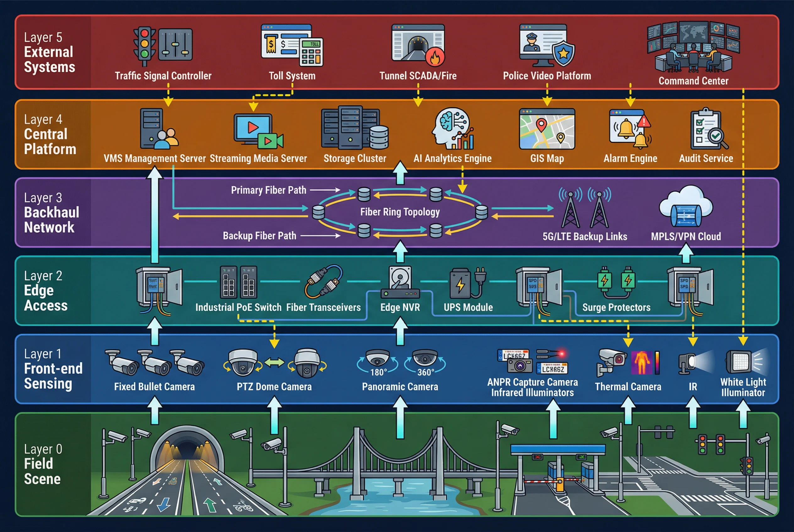
Figure 0.1: Six-layer system architecture — from field scene through front-end sensing, edge access, backhaul network, central platform, to external systems integration
Main Functions
The system operates as a closed-loop road event management cycle, progressing through six interconnected functional phases. Each phase builds on the previous one to ensure that every road event is not only observed but also acted upon and documented. Supporting capabilities — time synchronization, access control and audit, redundancy and failover, and elastic capacity — underpin all six phases.
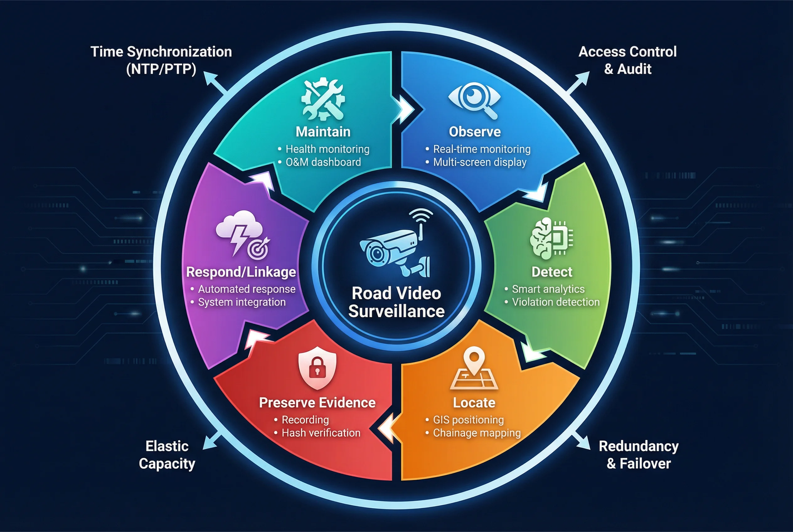
Figure 0.2: Road event closed-loop cycle — Observe, Detect, Locate, Preserve Evidence, Respond/Linkage, and Maintain, with supporting capabilities on the outer ring
Core Function Details
1. Real-time Situational Awareness
Operators see multi-lane, multi-site traffic status within seconds of an event. This is achieved through multi-stream encoding (main and sub streams), low-latency preview pipelines, and multi-screen wall layout templates that can be recalled instantly. Acceptance criteria include preview latency targets, frame continuity under load, layout switching time, and decode concurrency capacity.
2. Violation & Incident Discovery
Automated analytics reduce manual watch load and accelerate detection of wrong-way driving, congestion onset, stopped vehicles, and smoke or fire events. Analytics may run at the edge for low-latency alarms or at the central platform for easier model management. A rule engine with configurable confidence thresholds and false alarm tuning ensures operational practicality. Acceptance criteria include detection rate, false alarm rate, and event-to-ticket time.
3. Event Localization (GIS + Lane/Chainage)
Dispatch teams navigate directly to the precise spot — intersection arm, tunnel chainage, or bridge section — using camera geo-tags, direction metadata, and field-of-view polygon overlays on a GIS map. Acceptance criteria include location accuracy, map rendering speed, and correlation with external system data.
4. Evidence Capture & Forensics Package
Admissible evidence requires a timestamp, watermark, and integrity hash. The system enforces locked retention policies, exports evidence with cryptographic hash and digital signature, maintains a full audit trail, and relies on time synchronization to ensure chain-of-custody integrity. Acceptance criteria include export format compliance, hash verification, and playback consistency.
5. Inter-System Linkage Response
Coordinated actions — such as calling a VMS preset when a signal alarm fires, or triggering a PTZ tour when tunnel smoke is detected — are implemented via API and SDK integrations, message bus architectures, dry-contact I/O gateways, and workflow templates. Acceptance criteria include linkage success rate, fail-safe behavior under partial failures, and rollback rules.
6. Sustainable O&M
Reduced mean time to repair, proactive component replacement, and predictable lifecycle cost are achieved through device heartbeat monitoring, link quality tracking, storage health dashboards, and configuration backup automation. Acceptance criteria include alarm coverage completeness, MTTR metrics, and spare strategy validation.
Chapter Navigation
This guide is organized into twelve chapters, each addressing a distinct engineering domain. Navigate directly to any chapter using the cards below or the left sidebar.
Design Assumptions & Baseline
This guide is calibrated to a typical mainland urban and highway deployment context and aligns with common practice in public security and traffic management projects. Where local standards differ — such as GDPR-like privacy rules or different electrical codes — the acceptance and retention parameters must be adjusted accordingly. The following table summarizes the key baseline assumptions that underpin all engineering recommendations in this guide.
| Domain | Baseline Assumption | Adjustment Notes |
|---|---|---|
| Video Encoding | H.265 default; H.264 as fallback for legacy decoders; Mainstream profile, CBR/VBR | Adjust if decoder fleet is H.264-only |
| Resolution & Frame Rate | Live monitoring 1080p–4MP @ 25/30 fps; evidence capture 2–8MP with tuned shutter/IR | Higher resolution for specific evidence requirements |
| Network Architecture | Edge aggregation at roadside cabinets; fiber backhaul preferred; LTE/5G as secondary | Wireless-first for sparse remote points |
| Storage | Centralized VMS/NVR cluster; optional edge storage for intermittent links; 30-day retention default | Compliance may require 60–90 days |
| Power | AC 220V or DC 48V at roadside; PoE/PoE++ for short runs; surge protection mandatory | DC 48V for long runs and bridge deployments |
| Time Sync | NTP/PTP hierarchy; drift ≤ 1 s across devices for evidence workflows | Tighter if ANPR transaction correlation is strict |
| Operations | Quarterly preventive maintenance; 24/7 alarm handling; spare parts within city limits | Remote sites need extended spare kits |
| Integration | Traffic signal controller, incident platform, GIS, ANPR/vehicle analytics; ONVIF/RTSP/GB28181-like protocols | Proprietary protocols require adapter layer |
| Environment | Outdoor cameras: -30°C to +60°C, IP66/67, high glare/low light, vibration, soot/dust in tunnels | Salt fog near coastal roads requires enhanced corrosion protection |