Chapter 11. Installation & Debugging
Installation requirements, step-by-step procedures, and commissioning guidelines for road video surveillance systems
The quality of installation is as important as the quality of the equipment itself. A high-quality camera installed incorrectly — at the wrong height, wrong angle, with poor cable management, or without proper grounding — will fail to deliver the specified performance and will have a significantly shorter service life than a correctly installed equivalent. This chapter provides the detailed installation requirements, procedures, and commissioning guidelines that must be followed to achieve a reliable, high-performance road surveillance system.
11.1 Installation Requirements — Site Preparation
Before installation begins, the site must be prepared to ensure safe working conditions and to verify that the civil works (pole foundations, cable ducts, and cabinet pads) have been completed to the required standard. The following photograph shows a typical road surveillance installation in progress, illustrating the key requirements for a professional installation.
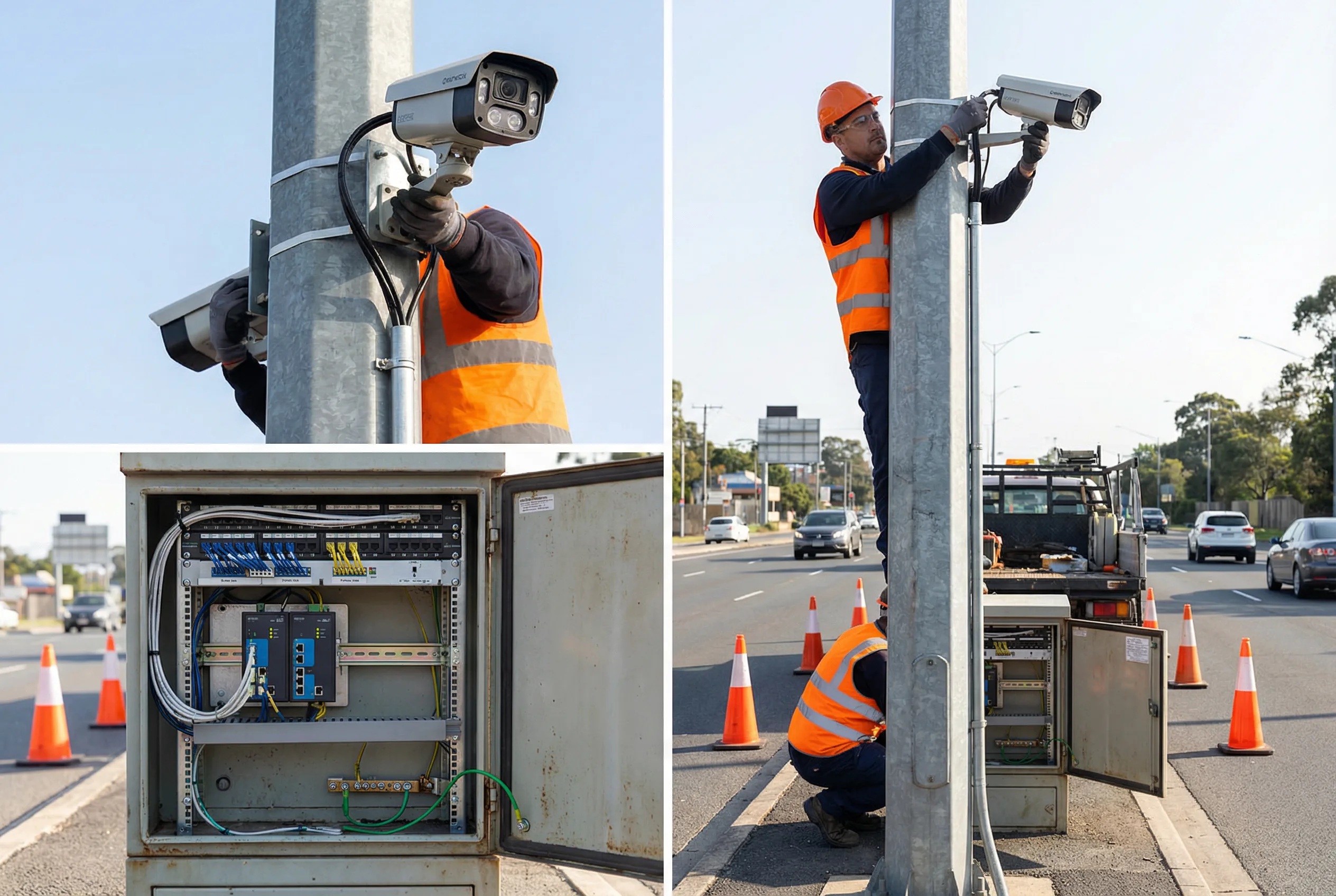
Figure 11.1: Professional road surveillance camera installation — technicians in high-visibility safety vests and hard hats installing an ANPR bullet camera on a 6-meter galvanized steel pole. The roadside cabinet is open showing neat cable management with labeled cables, industrial PoE switch, and fiber patch panel. Safety cones are placed around the work area. Key installation requirements visible: cables in conduit, proper grounding cable, neat cable ties, and professional wiring inside the cabinet.
11.2 Camera Mounting Requirements
Camera mounting is the most critical installation step, as the mounting position and angle directly determine the camera's coverage and image quality. The following requirements apply to all camera mounting installations and must be verified during the installation inspection phase of the acceptance test.
| Requirement | Specification | Verification Method |
|---|---|---|
| Mounting Height | ANPR: 5–7 m; PTZ: 6–10 m; Fixed: 4–8 m (per design) | Measure with laser distance meter; ± 0.1 m tolerance |
| Tilt Angle | ANPR: 15–25° from horizontal (per design); Fixed: per design | Measure with digital inclinometer; ± 1° tolerance |
| Pan Orientation | Camera axis aligned with road centerline; ± 2° tolerance | Verify on live image; lane lines should be parallel to image edges |
| Bracket Torque | All bolts torqued to specification (typically 20–30 Nm for M8) | Check with calibrated torque wrench; mark after torquing |
| Vibration | Camera must not vibrate visibly during normal traffic; use vibration-damping mount if required | Visual inspection during traffic; check image for blur |
| Sun Shield | Camera sun shield oriented to prevent direct sun in lens during peak hours | Check at midday; verify no lens flare on image |
| Cable Entry | Cable entry at bottom of camera housing; drip loop formed; cable gland tight | Visual inspection; pull test on cable gland |
11.3 Cable Installation Requirements
Cable installation quality directly affects system reliability. Poorly installed cables are the leading cause of intermittent faults and early failures in road surveillance systems. The following requirements apply to all cable installations and must be verified during the installation inspection.
| Cable Type | Installation Requirement | Common Defects to Avoid |
|---|---|---|
| Cat6 (PoE) | In conduit for all outdoor runs; minimum bend radius 4× cable OD; no sharp bends; cable ties at 300 mm intervals; labeled at both ends | Kinking; exceeding bend radius; water ingress at conduit entry; unlabeled cables |
| Fiber Optic | Minimum bend radius 30 mm; no tension on fiber; splice closure sealed IP68; fiber slack coiled at each splice; OTDR tested after installation | Excessive bending; tension on fiber; unsealed splice closures; no slack at splices |
| AC Power Cable | In separate conduit from data cables; minimum 30 mm separation; labeled at both ends; SPD installed at cabinet entry | Mixed with data cables; no SPD; unlabeled; exposed conductors |
| Grounding Cable | Copper flat strap or 16 mm² green/yellow cable; continuous from cabinet to earth rod; no joints; labeled | Joints in grounding cable; undersized cable; poor connection at earth rod |
11.4 Cabinet Wiring Requirements
The roadside cabinet must be wired to a professional standard that enables safe and efficient maintenance. The following requirements apply to all cabinet wiring installations. A cabinet that does not meet these requirements should be rewired before the installation inspection is conducted.
- All cables must be labeled at both ends with permanent labels matching the cable schedule in the as-built documentation.
- Power and data cables must be routed in separate cable trays or bundles, with a minimum separation of 30 mm.
- All cable entries must use cable glands of the correct size; unused entries must be sealed with blanking plugs.
- All equipment must be secured to DIN rail or rack with the correct hardware; no loose equipment inside the cabinet.
- The cabinet interior must be clean and free of cable offcuts, packaging, and debris before the installation inspection.
- A laminated wiring diagram must be affixed inside the cabinet door showing the complete internal wiring layout.
- The cabinet door must close and lock correctly; the seal must be intact and undamaged.
11.5 Commissioning Procedure
Commissioning is the process of bringing the installed system into operational service. It includes configuring all devices, verifying network connectivity, adjusting camera positions, and confirming that all system functions work correctly. The following table provides the step-by-step commissioning procedure.
| Step | Activity | Required Tools/Access | Completion Criterion |
|---|---|---|---|
| 1 | Power up all field equipment in sequence; verify no faults | Multimeter; cabinet key | All LEDs green; no fault indicators |
| 2 | Verify network connectivity from each camera to NVR | Laptop with IP scanner; VMS client | All cameras visible on network; ping successful |
| 3 | Configure IP addresses, VLAN, and QoS on all switches | Switch management interface; network plan | All switches configured per network plan |
| 4 | Configure camera parameters (resolution, bitrate, codec, NTP) | Camera web interface or VMS | All cameras on H.265; NTP synchronized; bitrate per design |
| 5 | Adjust camera position and focus; verify coverage | Live image on laptop; alignment tool | All lanes covered; image sharp; no obstructions |
| 6 | Configure ANPR parameters (trigger, sensitivity, plate format) | ANPR configuration tool | Plates captured correctly in test; accuracy ≥ 95% |
| 7 | Configure PTZ presets and auto-tracking | PTZ control interface | All presets set; auto-tracking verified |
| 8 | Configure recording schedules and retention on NVR | NVR management interface | All cameras recording; retention period set correctly |
| 9 | Test ERPS ring failover; verify recovery time | Fiber disconnect; packet loss counter | Recovery < 50 ms; no recording loss |
| 10 | Conduct full system walkthrough with client; demonstrate all functions | VMS client; operator workstation | Client sign-off on commissioning checklist |
11.6 Common Installation Defects and Remediation
The following table lists the most common installation defects found during acceptance inspections of road surveillance systems, along with the required remediation action for each defect. Contractors should use this table as a self-inspection checklist before submitting the installation for formal acceptance.
| Defect | Impact | Remediation |
|---|---|---|
| Camera not level; tilted sideways | Distorted coverage; poor ANPR accuracy | Re-level camera; re-verify coverage |
| Focus not optimized for target distance | Blurry image at target; poor plate readability | Re-focus with focus test chart at target distance |
| IR illuminator aimed incorrectly | Uneven illumination; hotspot or dark areas | Re-aim illuminator; verify uniform illumination on night image |
| No drip loop on cable at camera | Water ingress into camera housing; early failure | Re-route cable with drip loop; reseal cable entry |
| Earth resistance > 4 Ω | Inadequate lightning protection; equipment damage risk | Add additional earth rods; use ground enhancement compound |
| Cables not labeled | Maintenance difficulty; risk of incorrect disconnection | Label all cables per cable schedule; update as-built documentation |
| Default camera passwords not changed | Security vulnerability; unauthorized access risk | Change all passwords immediately; update password register |
| NTP not configured or inaccurate | Incorrect timestamps; evidence inadmissible | Configure NTP on all cameras; verify synchronization |