Chapter 1. System Components
Architecture, component functions, working principles, and deployment boundaries
1.1 System Architecture
The road video surveillance system is organized around four deployment boundaries: the Field Side, the Edge Side, the Central Side, and the External Side. This boundary model is fundamental to understanding responsibility, failure isolation, and interface design. The Field Side encompasses all physical sensing and mounting hardware deployed at road points. The Edge Side aggregates field devices at roadside cabinets and provides local protection and connectivity. The Central Side hosts all platform services, storage, and analytics. The External Side represents partner systems that exchange data with the surveillance platform through defined interfaces.
Deployment boundary discipline is critical: the system boundary includes all devices from camera lens to storage media and platform services. External systems are integrated via defined interfaces and must not be tightly coupled to avoid cascading failures. This means that a failure in the toll system, for example, must not prevent the surveillance platform from recording or exporting evidence independently.
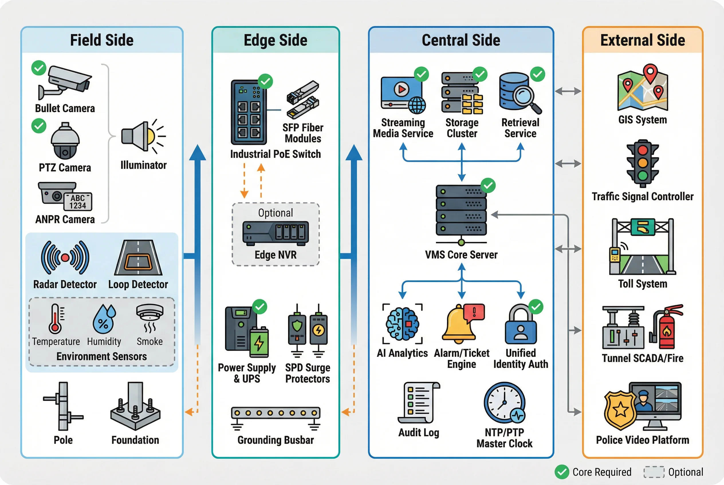
Figure 1.1: Four-zone system architecture — Field Side, Edge Side, Central Side, and External Side with data flow arrows and core/optional component markings
1.2 Component List & Functions
The system comprises seven major subsystem categories, each with distinct inputs, outputs, key performance indicators, and mismatch risks. The component breakdown tree below illustrates how each category decomposes into specific devices and their associated performance parameters. Understanding these KPIs and mismatch risks is essential for procurement, acceptance testing, and troubleshooting.
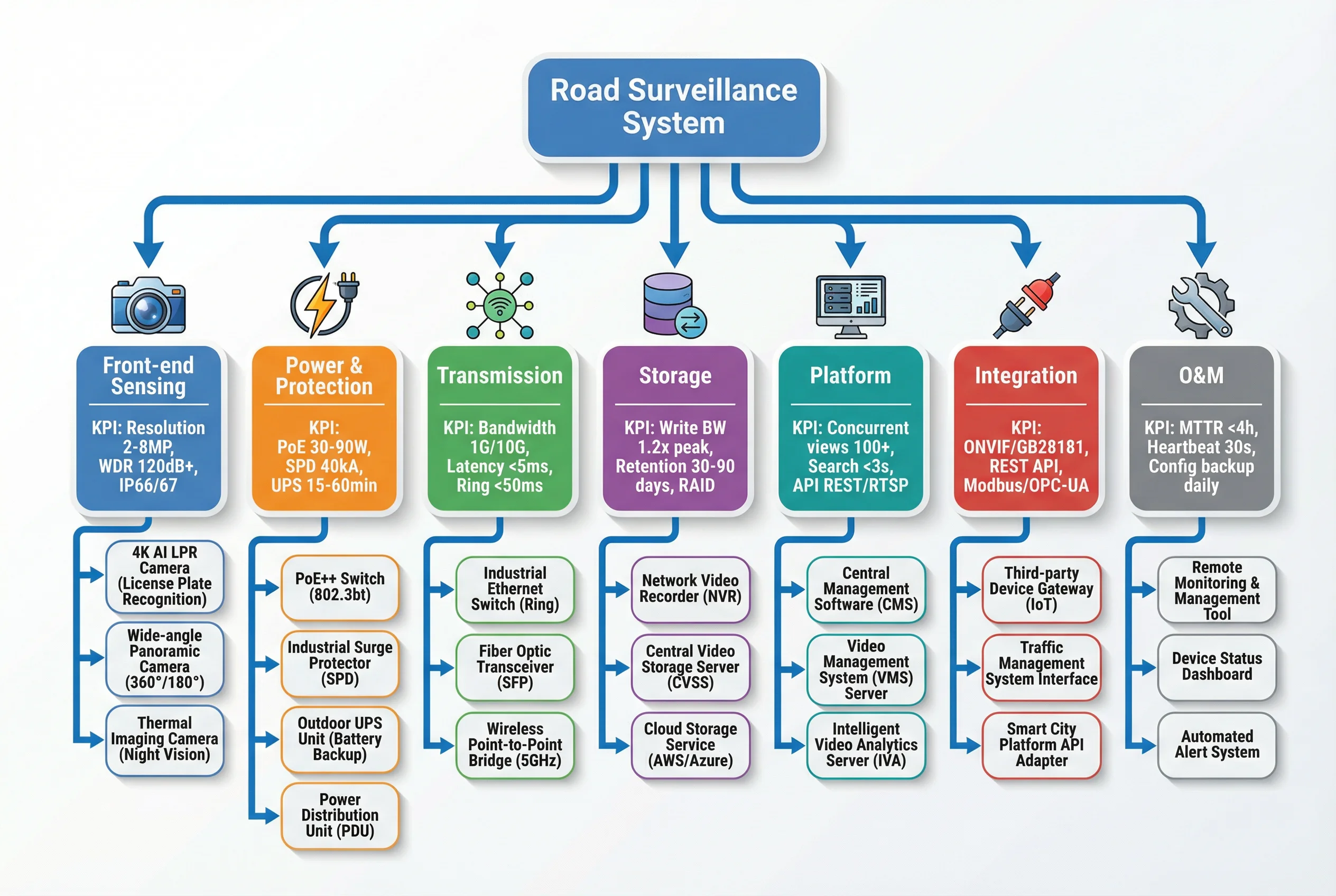
Figure 1.2: Component breakdown tree — Road Surveillance System decomposed into seven subsystem categories with KPIs and sub-components
Key Component Specifications
The following table provides a structured overview of each major component category, covering its primary I/O interfaces, key performance indicators, and the consequences of specification mismatches. This table should be used as a checklist during design review and procurement.
| Component | Primary I/O | Key Performance Indicators | Mismatch Risk |
|---|---|---|---|
| ANPR / Capture Camera | Trigger input (radar/virtual line); snapshot + metadata output; dual video streams | Plate capture rate ≥95%; shutter ≤1/1000s; WDR ≥120dB; IR performance at speed | Wrong focal length → insufficient pixels on plate; poor IR → overexposure at night |
| Fixed Bullet Camera | RTSP/ONVIF stream; alarm inputs (optional); device telemetry | WDR ≥120dB; low-light SNR ≥52dB; IP66/67; operating temp -30°C to +60°C | Consumer-grade outdoor use → fogging, poor reliability, early failure |
| PTZ Camera | Video stream; PTZ control; preset/tour commands | Rotation speed ≥200°/s; preset accuracy ±0.1°; optical zoom ≥20×; stabilization | Insufficient stabilization on bridge vibration → unusable zoom images |
| Illuminators (IR/White) | Power input; photocell/remote control | Illumination uniformity ≥80%; wavelength match to sensor; thermal management | Glare to drivers; plate overexposure; regulatory non-compliance |
| Roadside Cabinet / Pole Box | Power distribution; fiber termination; patch panel | IP55 min (IP66 preferred); corrosion resistance; thermal design ≤55°C internal | Undersized cabinet → overheating, maintenance impossible, equipment failure |
| Industrial PoE Switch | PoE ports (8–24); SFP uplinks; VLAN/QoS; ring protocols (ERPS/RSTP) | PoE budget ≥240W; surge immunity ≥4kV; -40°C to +75°C; ring convergence <50ms | Insufficient PoE budget → camera brownout; no ring support → large outage on fiber cut |
| Backhaul (Fiber/Wireless/Cellular) | Ethernet/IP transport; primary and backup paths | Throughput ≥1G (10G for dense nodes); latency <5ms; availability ≥99.9%; protection switching <50ms | Oversubscription → dropped frames, export failure, evidence gaps |
| Central Storage (NVR Cluster / VMS Storage) | Ingest streams; store; playback/export | Write bandwidth ≥1.2× peak ingest; retention 30–90 days; RAID-6 or erasure coding; rebuild time <24h | RAID rebuild too slow → risk of second disk failure causing data loss |
| VMS Platform | Device management; user access; events; REST/SDK APIs | Concurrent views ≥100; search speed <3s; alarm throughput ≥1000/min; audit log integrity | Licensing model mismatch → cost explosion at scale; API incompatibility → integration failure |
| Time Sync (NTP/PTP) | Time signal distribution; drift monitoring | Drift ≤1s across all devices; stratum hierarchy; holdover ≥24h on GPS loss | Time inconsistency → evidence disputes, ANPR correlation failures, audit gaps |
1.3 Working Principle
Startup Sequence
On power-on, the roadside cabinet initiates a controlled startup sequence. The switch boots first and begins PoE sequencing to cameras, which prevents simultaneous inrush current from tripping breakers. Cameras perform a power-on self-test, acquire their IP address via DHCP or static configuration, and register with the VMS. The VMS validates device identity, pushes configuration templates (stream profiles, recording policies, analytics zones), and begins ingesting streams. Time synchronization is established within the first minute; devices that fail to sync within the configured threshold are flagged for operator attention.
Normal Operation
During normal operation, cameras stream continuously to the edge switch, which forwards traffic over the backhaul ring to the central ingest service. The storage cluster writes continuous recording streams and event clips simultaneously. The analytics engine processes video streams — either at the edge or centrally — and produces alarm events with metadata. The VMS correlates alarms with GIS coordinates and presents them to operators on the monitoring wall. Operators can view live feeds, review recordings, export evidence packages, and issue PTZ control commands. All actions are logged in the audit trail.
Exception Handling
The system is designed to handle three major exception classes gracefully, each with defined detection, response, and recovery procedures.
| Exception | Detection | Immediate Response | Recovery | Acceptance Test |
|---|---|---|---|---|
| Backhaul Fiber Cut | VMS ingest alarms; packet loss spike on ring segment | Ring protocol reroutes traffic in <50ms; if edge NVR present, local caching begins | After link restoration, backlog sync uploads to central; evidence gap occurs if no edge storage | Alarm within defined seconds; operator notification; no config loss |
| Lightning Surge on Pole | SPD clamps surge; PoE switch port may trip; camera offline alarm | UPS ride-through maintains power; auto-reclose breaker; switch PoE port power-cycle | Repeated surge triggers require grounding resistance re-test and SPD replacement | Camera recovery time; SPD indicator check; grounding resistance measurement |
| Time Server Drift/Failure | VMS detects drift > threshold; devices hold last sync | VMS blocks evidence export or annotates "time untrusted"; operator alert | Switch to backup NTP; correct drift; re-sign evidence chain | Drift log review; export block verification; backup NTP failover test |