Chapter 7. Support & Integration
Supporting systems, third-party integration requirements, and ecosystem dependencies for road video surveillance
A road video surveillance system does not operate in isolation. It depends on a range of supporting systems for power, network connectivity, time synchronization, and operational management, and it must integrate with external systems such as traffic management centers, police databases, toll collection systems, and emergency response platforms. The design of the supporting system ecosystem is as important as the design of the surveillance system itself, and failures in supporting systems are a leading cause of surveillance system downtime.
7.1 Supporting Equipment Integrated Overview
The following diagram presents all supporting equipment categories integrated in a single view, showing how each category contributes to the overall system. The six categories — power supply, network infrastructure, mounting hardware, environmental protection, illumination, and grounding and lightning protection — must all be designed and procured as part of the surveillance system, not as afterthoughts.
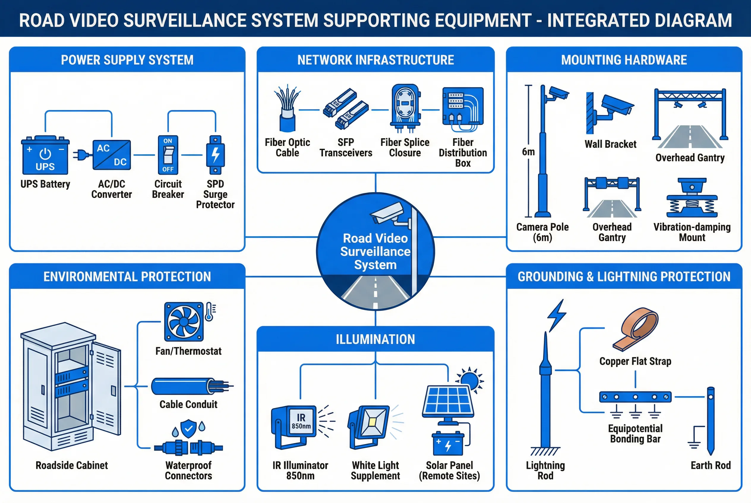
Figure 7.1: Integrated supporting equipment diagram for road video surveillance systems — six categories: Power Supply System (UPS, AC/DC converter, circuit breaker, SPD), Network Infrastructure (fiber cable, SFP transceivers, splice closure, distribution box), Mounting Hardware (camera pole, wall bracket, overhead gantry, vibration-damping mount), Environmental Protection (roadside cabinet, fan/thermostat, cable conduit, waterproof connectors), Illumination (IR illuminator, white light supplement, solar panel), and Grounding & Lightning Protection (lightning rod, copper flat strap, equipotential bonding bar, earth rod).
7.2 Power Supply System Requirements
The power supply system is the most critical supporting system, as all other systems depend on it. Road surveillance deployments face diverse power supply conditions, from reliable grid power at urban intersections to unreliable or absent grid power at remote highway locations. The power supply design must address the specific conditions of each deployment location.
| Component | Specification | Selection Notes |
|---|---|---|
| UPS Battery (VRLA) | 12V; capacity for 30 min at full load; -20°C to +60°C | Derate capacity by 20% per 10°C above 25°C ambient |
| AC/DC Converter | AC 220V to DC 48V; efficiency ≥ 90%; output regulation ± 2% | Size for 150% of maximum load; include short-circuit protection |
| Circuit Breaker | 20A, 2-pole; rated for outdoor use; IEC 60947-2 | Size for 125% of maximum load current |
| SPD (Type 2) | Uc ≥ 275V; Imax ≥ 20 kA; response time < 25 ns | Replace after any lightning event exceeding rated Imax |
| Solar Panel (remote) | 100–300W per node; MPPT controller; battery bank for 3 cloudy days | Size for worst-case solar irradiance at deployment latitude |
| Cabinet Fan/Thermostat | Thermostat-controlled; activate at 40°C; IP54 fan | Size fan for cabinet heat load; include filter for dust environments |
7.3 Network Infrastructure Requirements
The network infrastructure supporting a road surveillance system includes the fiber optic cable plant, the fiber splice closures and distribution boxes, the SFP transceivers, and the cable management systems. Each component must be specified for the environmental conditions of the deployment and must be installed by qualified personnel using proper tools and procedures.
| Component | Specification | Selection Notes |
|---|---|---|
| Fiber Optic Cable | G.652D single-mode; 12–48 fibers; HDPE outer jacket; armored for direct burial | Use dielectric cable to avoid lightning coupling; armored for rodent protection |
| SFP Transceiver (MM) | 1000BASE-SX; 850 nm; 550 m range; LC connector | Use for short runs (< 500 m) within a facility |
| SFP Transceiver (SM) | 1000BASE-LX; 1310 nm; 10–80 km range; LC connector | Use for field-to-aggregation runs; match to fiber span length |
| Fiber Splice Closure | IP68; 48 splice capacity; inline or dome type; UV-resistant | Use inline type for cable runs; dome type for branch points |
| Fiber Distribution Box | Wall-mount or pole-mount; 12–24 port; SC/LC adapters; IP65 | Install at each aggregation point; include patch panel for flexibility |
| Cable Conduit | HDPE or PVC; 32–50 mm ID; UV-resistant; pull wire pre-installed | Use HDPE for direct burial; PVC for above-ground runs |
7.4 Third-Party System Integration
Road surveillance systems must integrate with a range of external systems to deliver their full operational value. The integration requirements vary by deployment type and operational context, but the following integrations are common across most road surveillance deployments.
| External System | Integration Type | Data Exchange | Protocol/Standard |
|---|---|---|---|
| Traffic Management Center (TMC) | Bidirectional; real-time | Live video feeds; incident alarms; PTZ control commands | ONVIF; proprietary SDK; NTCIP |
| Police ANPR Database | Outbound; real-time | License plate reads; vehicle images; location/timestamp | REST API; SOAP; proprietary |
| Toll Collection System | Bidirectional; real-time | ANPR captures; transaction correlation; fee evasion alerts | REST API; database integration |
| Emergency Response (112/911) | Outbound; event-triggered | Incident alarms; video clips; location data | CAD integration; REST API |
| Tunnel SCADA | Bidirectional; real-time | Fire/smoke alarms; ventilation control triggers; VMS alerts | Modbus; OPC-UA; proprietary |
| Variable Message Signs (VMS) | Outbound; event-triggered | Incident messages; speed limit changes; lane closure | NTCIP 1203; proprietary |
| Weather Monitoring | Inbound; periodic | Visibility, precipitation, wind speed (affects camera settings) | REST API; MQTT; proprietary |
7.5 Mounting Hardware and Environmental Protection
The mounting hardware and environmental protection systems ensure that cameras and field equipment remain operational throughout their design life despite exposure to weather, vibration, corrosion, and physical impact. The selection of mounting hardware must account for the specific environmental conditions of each deployment location, including wind loading, seismic zone, salt-fog exposure, and ambient temperature range.
| Component | Specification | Environmental Consideration |
|---|---|---|
| Camera Pole (standard) | Hot-dip galvanized steel; 6–8 m; base plate with anchor bolts; wind load per local code | Coastal: stainless steel or duplex coating; seismic: reinforced base |
| Overhead Gantry | Structural steel; span per road width; wind load per local code; access walkway | Coastal: hot-dip galvanized + paint; bridge: vibration analysis required |
| Vibration-Damping Mount | Elastomeric isolator; rated for camera weight × 5 (dynamic load); stainless steel hardware | Required on bridges and gantries with significant traffic-induced vibration |
| Roadside Cabinet | Powder-coated steel; IP55; IK10; fan + thermostat; security lock grade 3; anchor bolts | Coastal: stainless steel; hot climate: additional ventilation; cold climate: heater |
| Waterproof Connectors | IP67 RJ45 connectors for outdoor cable runs; UV-resistant housing | Required for all outdoor cable connections not inside cabinet or conduit |