Chapter 10. Quality & Acceptance
Quality standards, acceptance testing procedures, and performance benchmarks for road video surveillance systems
Quality assurance and acceptance testing are the final gatekeepers before a road surveillance system enters operational service. A rigorous acceptance process verifies that the installed system meets the specified performance requirements, that all components are correctly installed and configured, and that the system is ready for the operational demands of continuous 24/7 surveillance. Acceptance testing should be conducted by an independent party with reference to the project specifications and the applicable national and international standards.
10.1 Image Quality Comparison
The most visible quality dimension of a road surveillance system is image quality. The following comparison illustrates the difference between a poorly specified or installed system and a correctly specified high-quality system. The key quality dimensions — resolution, WDR, noise level, and sharpness — directly determine whether the system can fulfill its operational purpose of license plate capture, incident detection, and evidence recording.
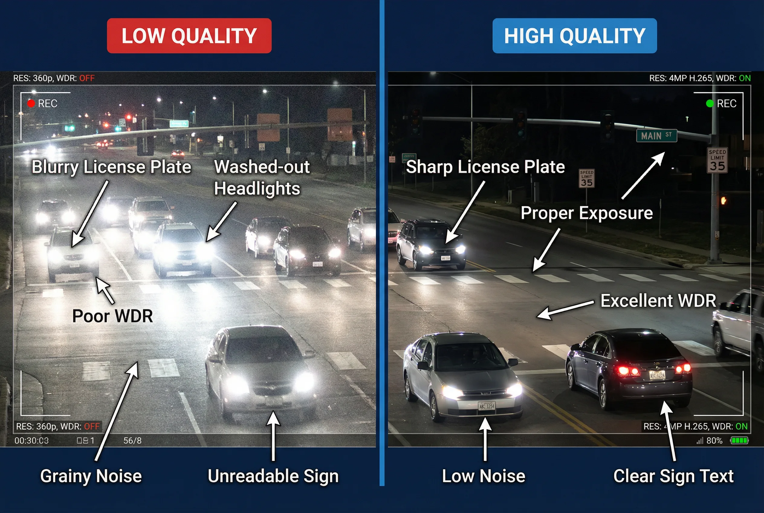
Figure 10.1: Image quality comparison between a low-quality road surveillance camera (left) and a high-quality 4MP H.265 camera with true WDR (right). Key differences: resolution, WDR performance, noise level, license plate readability, and sign text clarity. The high-quality image shows sharp license plate text, proper exposure on both headlights and shadows, and low noise — all essential for evidence-grade surveillance.
10.2 Image Quality Acceptance Criteria
The following table defines the minimum image quality acceptance criteria for road surveillance cameras. These criteria must be verified during the acceptance test using the test procedures described in section 10.4. Cameras that do not meet these criteria must be adjusted, replaced, or the design must be revised before acceptance can be granted.
| Quality Criterion | ANPR Camera | PTZ Camera | Fixed Camera | Test Method |
|---|---|---|---|---|
| License Plate Readability | 100% at design speed; ≥ 250 px/m at plate | N/A (not primary function) | N/A | Vehicle test at design speed; 20 consecutive plates |
| WDR Performance | No washout or silhouette at ≥ 120 dB scene contrast | No washout at ≥ 100 dB | No washout at ≥ 100 dB | Backlit test scene; evaluate at sunrise/sunset |
| Night Image Quality | Plate readable at design speed with IR only | Object identifiable at 50 m in darkness | Scene overview in darkness | Night test with all ambient lighting off |
| Motion Blur | No blur on plate at design speed (e.g., 120 km/h) | No blur at PTZ tracking speed | Acceptable blur at 80 km/h | Vehicle test at design speed; evaluate sharpness |
| Coverage | All lanes fully covered; no blind spots | 360° pan verified; all presets reachable | Design FOV verified; no obstructions | Walk test; verify all lanes and approaches |
10.3 System Performance Acceptance Criteria
Beyond image quality, the system must meet performance criteria for availability, recording continuity, network reliability, and storage integrity. The following table defines the minimum system performance acceptance criteria.
| Performance Criterion | Minimum Requirement | Test Method |
|---|---|---|
| System Availability | ≥ 99.5% over 30-day test period | Monitor all cameras for 30 days; calculate uptime |
| Recording Continuity | No recording gaps > 1 second; < 0.1% total gap time | Review recording logs; verify no gaps in 7-day sample |
| ERPS Failover Time | < 50 ms on fiber ring cut | Disconnect fiber; measure time to recovery with packet loss counter |
| NTP Synchronization | All cameras within ± 1 second of GPS reference | Check timestamp on simultaneous event across all cameras |
| Storage Integrity | All recorded footage retrievable; no corruption | Random sample playback; hash verification of exported clips |
| ANPR Accuracy | ≥ 95% correct plate reads in daylight; ≥ 90% at night | Known plate test: 100 vehicles; count correct reads |
| PTZ Preset Accuracy | Return to preset within ± 0.1° of original position | Set preset; pan away; return; measure deviation |
| Video Latency | < 500 ms from camera to operator workstation | Measure latency with synchronized clock on camera and display |
10.4 Acceptance Test Procedures
The acceptance test should be conducted in three phases: pre-installation inspection, installation inspection, and functional testing. Each phase must be completed and signed off before proceeding to the next. The following table summarizes the key test procedures for each phase.
| Phase | Test Item | Procedure | Pass Criterion |
|---|---|---|---|
| Phase 1: Pre-Installation | Equipment verification | Check model numbers, serial numbers, and firmware versions against BOM | 100% match to approved BOM |
| Firmware verification | Verify firmware version on all devices; check against approved version list | All devices on approved firmware version | |
| Configuration backup | Export configuration from all devices; store in project documentation | Configuration backup complete for all devices | |
| Phase 2: Installation | Mechanical inspection | Inspect mounting hardware, cable management, grounding, and cabinet installation | All items per installation standard; no defects |
| Cable testing | Cat6 continuity and performance test; fiber OTDR test; earth resistance test | Cat6: TIA-568C pass; Fiber: loss < budget; Earth: < 4 Ω | |
| Power verification | Measure voltage at each PoE port; verify UPS switchover | PoE voltage 44–57V; UPS switchover < 20 ms | |
| Phase 3: Functional | Image quality test | Evaluate image quality per criteria in section 10.2 | All criteria met |
| ANPR accuracy test | 100 known-plate vehicle passes; count correct reads | ≥ 95% day; ≥ 90% night | |
| Network resilience test | Cut fiber ring; measure recovery time; verify no recording loss | Recovery < 50 ms; no recording loss | |
| 30-day availability trial | Monitor all cameras for 30 days; log all outages | Availability ≥ 99.5% |
10.5 Acceptance Documentation
The acceptance process must be documented with a formal acceptance report that includes the test results for all criteria, a list of any deficiencies found and their resolution status, and the signatures of the contractor, client, and independent inspector. The acceptance report becomes part of the project as-built documentation and is required for warranty claims and future maintenance reference.
- As-built drawings showing the final installed positions of all cameras, cabinets, and cable routes.
- Network diagram showing the final IP address assignments, VLAN configuration, and fiber ring topology.
- Equipment inventory with serial numbers, firmware versions, and warranty expiry dates for all devices.
- Configuration backups for all cameras, switches, NVRs, and management servers.
- Test results for all acceptance criteria, signed by contractor and client representatives.
- Training records showing that all operators and maintenance personnel have received the required training.
- Spare parts inventory confirming that the agreed initial spare parts stock is on-site.