Chapter 3. Scenarios & Selection
Eight deployment scenarios with real-world images, technical specifications, and selection guidance
Road video surveillance is not a single product but a family of deployment configurations, each shaped by the physical environment, traffic characteristics, evidence requirements, and operational constraints of the specific site. This chapter presents eight canonical deployment scenarios that collectively cover the full range of road environments encountered in practice. For each scenario, the discussion covers the environmental context, the imaging and coverage challenges, the recommended camera and system configuration, and the key technical indicators that must be verified during acceptance testing. The selection guidance at the end of each scenario provides a concise decision framework for engineers who must choose between competing approaches.
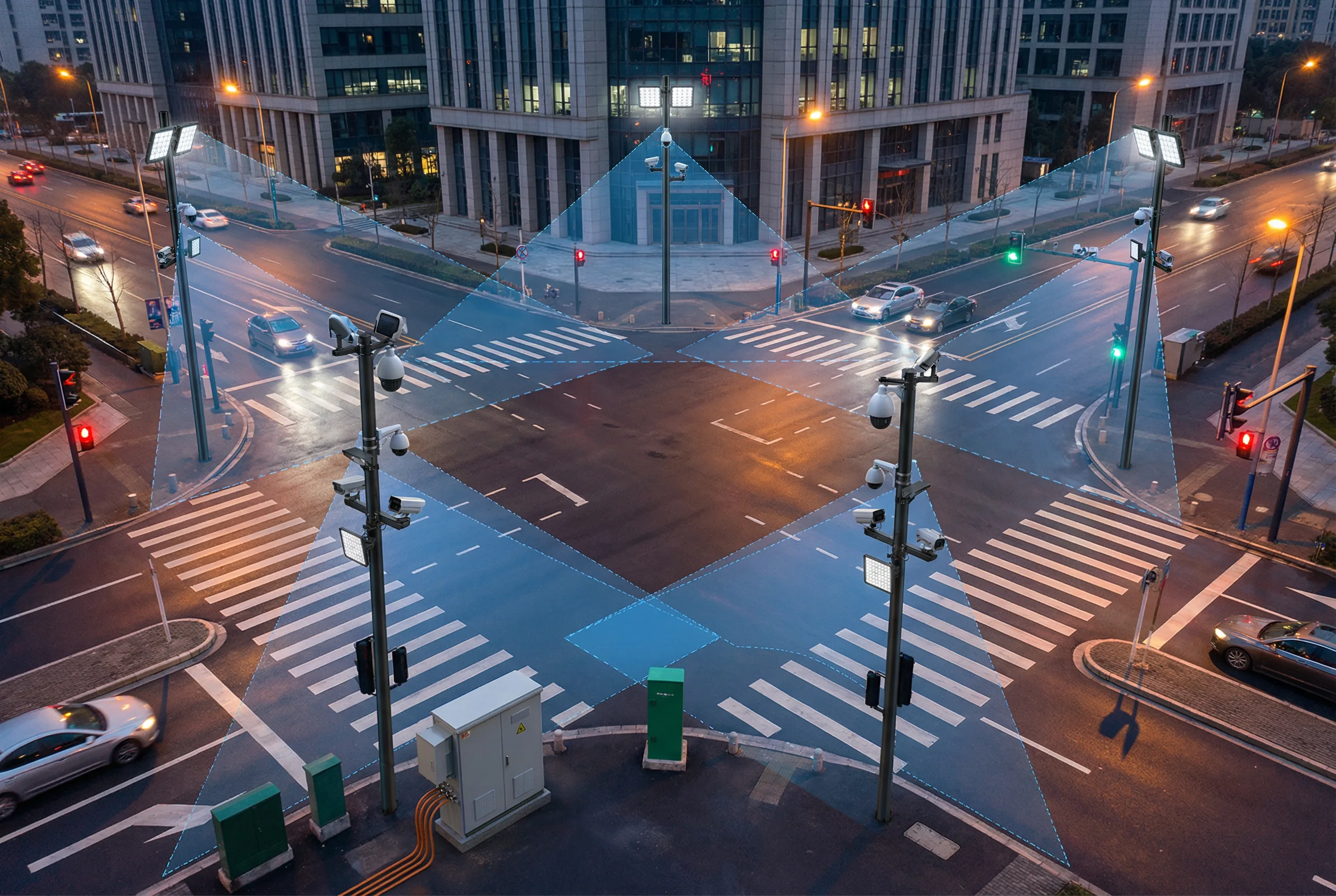
Figure 3.1: Urban intersection with full-coverage camera deployment — overview cameras on corner poles, ANPR cameras at stop lines, and IR illuminators for night operation. Blue overlays show camera field-of-view zones.
Urban intersections are the most complex surveillance deployment scenario due to the simultaneous need for wide-area situational awareness, lane-level violation capture, pedestrian monitoring, and signal-linked event response. A typical four-way signalized intersection requires a minimum of four camera positions — one per approach arm — with each position hosting an overview camera and a dedicated ANPR/capture camera. The overview camera provides situational context and supports incident detection analytics, while the capture camera delivers evidence-quality images of license plates at the stop line.
The primary imaging challenge is dynamic range: at dawn and dusk, one or two approach arms will be shooting directly into the sun, creating extreme backlight conditions. WDR performance of at least 120dB is mandatory, and camera mounting angles must be carefully chosen to minimize direct sun exposure. Night operation requires IR illuminators sized for the lane width and capture distance, with power tuned to avoid plate overexposure from high-reflectivity plates.
| Indicator | Specification | Acceptance Method |
|---|---|---|
| Plate capture rate | ≥ 95% day; ≥ 90% night | Drive-by test: 50 passes each condition |
| WDR performance | ≥ 120 dB; usable image in backlight | Backlight scene test at worst sun angle |
| Signal linkage | Alarm within 200 ms of signal phase change | Timestamp correlation test |
| Coverage continuity | No blind spots in stop line zone ± 15 m | Walk-through with calibration target |
| Night illumination | Uniform illumination; no plate overexposure | Night drive-by at 40 km/h and 60 km/h |
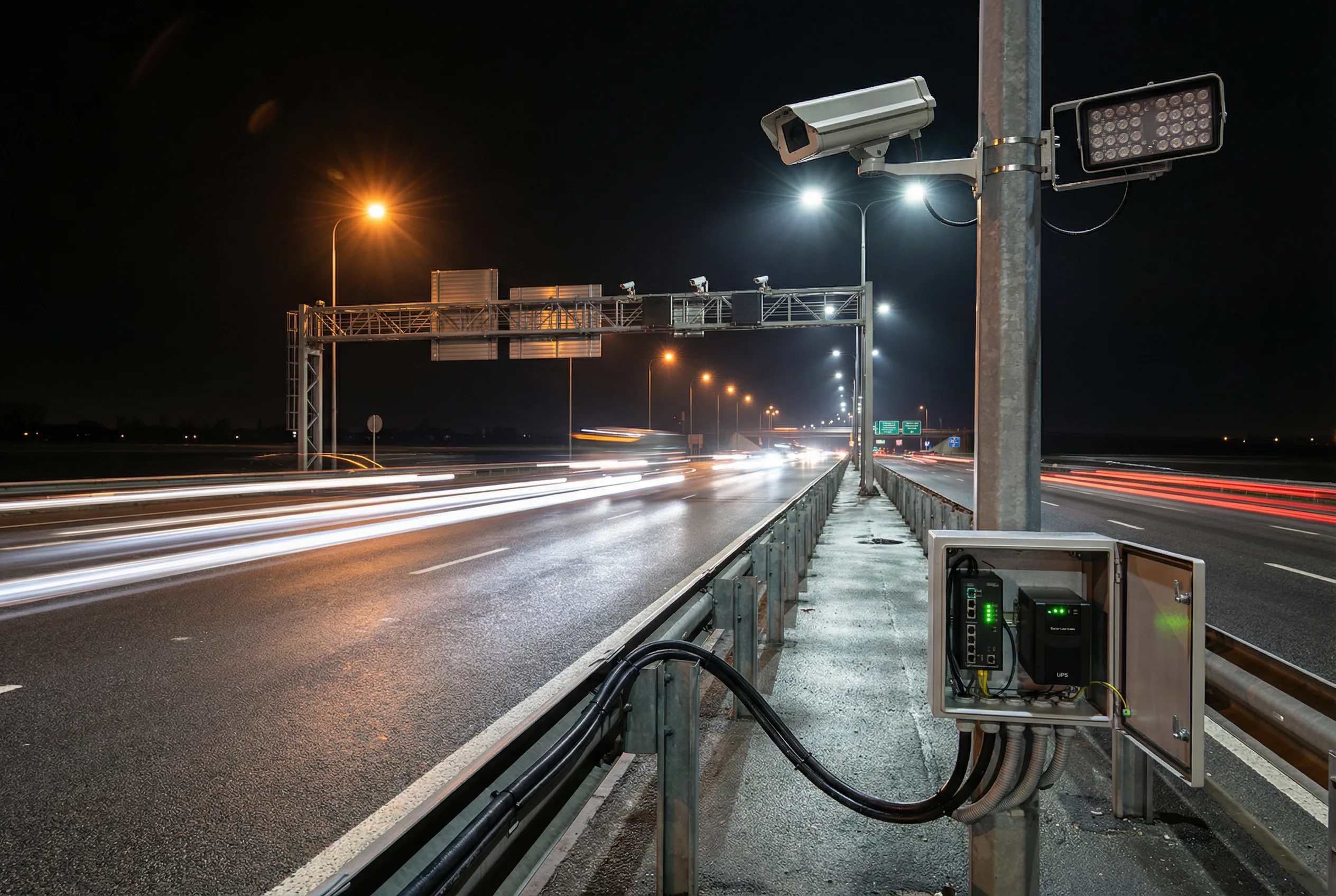
Figure 3.2: Highway mainline surveillance — roadside pole with long-focal-length capture camera, IR illuminator array, and roadside cabinet housing industrial PoE switch and UPS. Overhead gantry visible in the background.
Highway mainline surveillance presents the most demanding imaging challenge in road surveillance: vehicles traveling at 80–120 km/h must be captured with sufficient plate pixel density for evidence-grade identification. At these speeds, the effective exposure window for a plate at the design distance is typically 2–5 milliseconds, requiring a shutter speed of 1/1000 s or faster. This in turn requires either very bright illumination or a high-sensitivity sensor, and the two must be balanced to avoid overexposure.
Point spacing on highway mainlines is typically 500 m to 2 km, which means that each surveillance point must be self-sufficient with its own power, protection, and edge storage. Fiber backhaul runs along the highway shoulder, and the ring topology ensures that a single fiber cut does not cause a complete outage. Each roadside cabinet must be sized for the thermal environment — highway shoulders can reach 70°C in summer — and must include surge protection rated for the local lightning exposure level.
| Indicator | Specification | Acceptance Method |
|---|---|---|
| Plate capture rate at speed | ≥ 95% at 120 km/h | Drive-by test at design speed |
| IR illumination range | Uniform illumination to design distance | Night illumination measurement |
| Cabinet thermal | Internal temp ≤ 55°C at 40°C ambient | Temperature logger over 48h summer test |
| Fiber ring recovery | Traffic restoration < 50 ms on fiber cut | Fiber cut simulation test |
| Edge storage | Local recording continues during backhaul outage | Backhaul disconnect test; verify local playback |
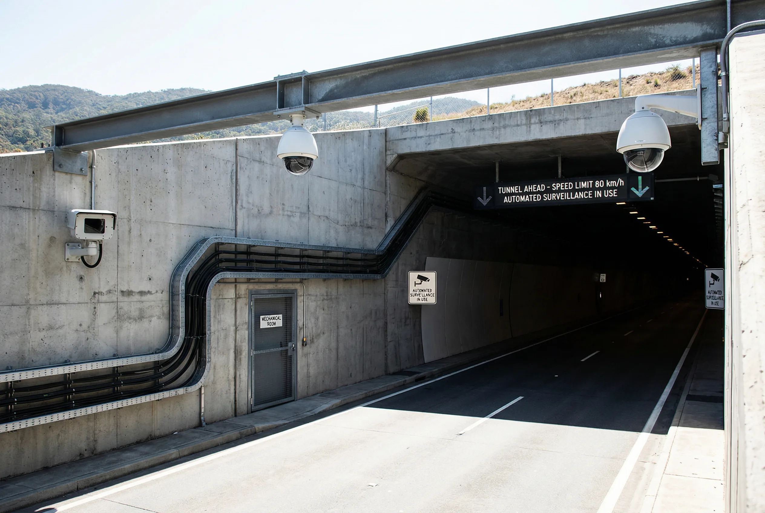
Figure 3.3: Tunnel portal surveillance — PTZ dome cameras on the overhead beam, fixed ANPR camera on the side wall, thermal camera for smoke detection, and cable tray routing to the mechanical room. Extreme WDR challenge visible.
The tunnel portal zone — typically 50–100 m outside and 50–100 m inside the tunnel entrance — is the most challenging WDR environment in road surveillance. The luminance ratio between the bright exterior and the dark tunnel interior can exceed 10,000:1, which is beyond the capability of standard cameras. This zone requires cameras with true WDR of at least 130 dB, and in some cases, two separate cameras — one optimized for the bright exterior and one for the dark interior — may be required to provide complete coverage.
The portal zone also requires thermal cameras for smoke and fire detection, as vehicle fires in tunnels are a critical safety event that must be detected within seconds. Thermal cameras are immune to the WDR challenge and provide reliable detection regardless of lighting conditions. The portal zone cameras must be mounted on the overhead beam or side wall, not on poles, to avoid obstruction of the lane clearance envelope.
| Indicator | Specification | Acceptance Method |
|---|---|---|
| WDR portal transition | Usable plate image during portal transition | Drive-through test at design speed; review 50 clips |
| Thermal fire detection | Alarm within 30 s of fire source | Controlled smoke test; measure alarm latency |
| Enclosure protection | IP66 minimum; soot-resistant coating | Visual inspection; IP rating certificate |
| Cable routing | Metal conduit; fire-rated cable in tunnel zone | Cable routing inspection; fire rating certificate |
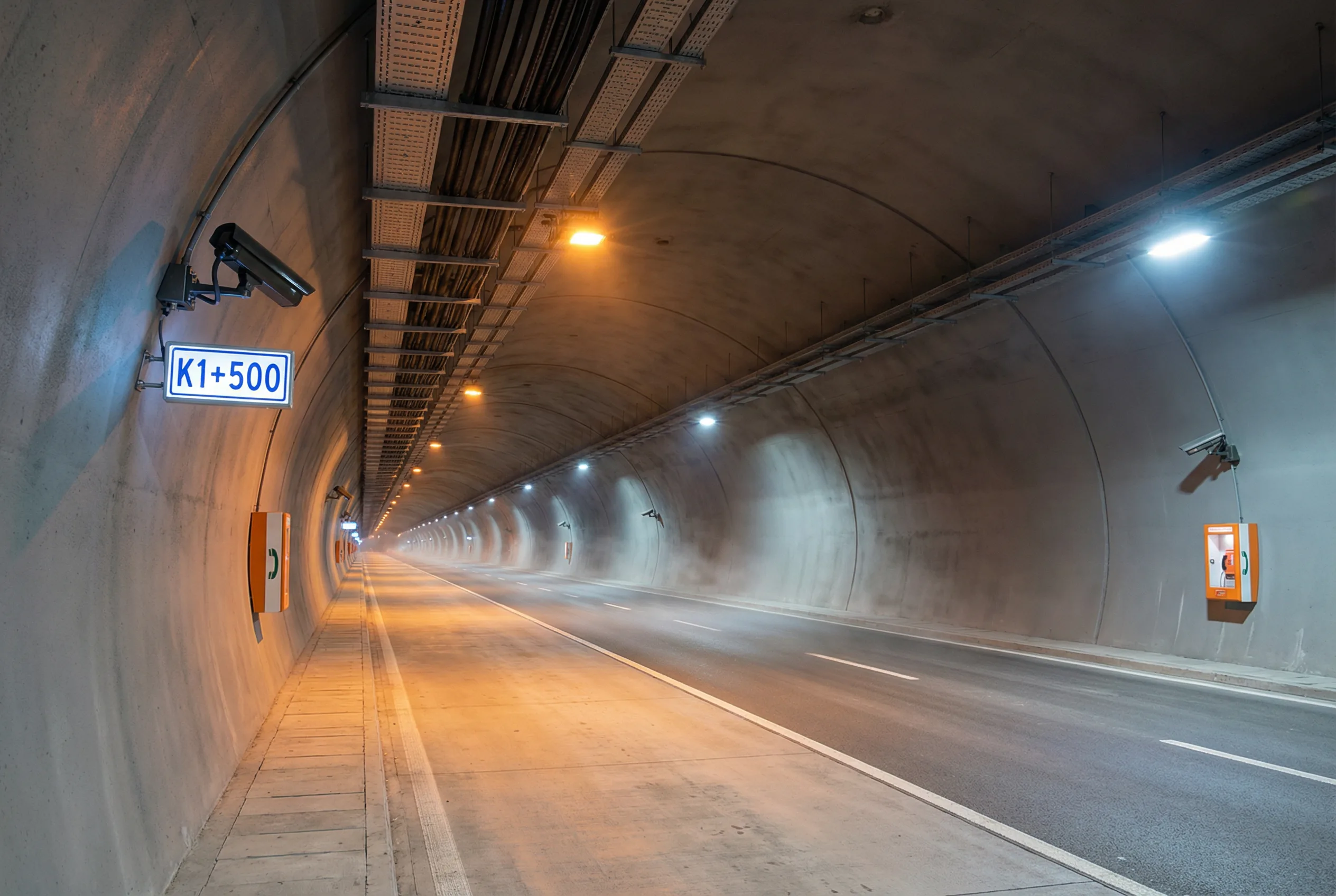
Figure 3.4: Tunnel interior surveillance — side wall mounted cameras at 100 m intervals with chainage markers (K1+500), ceiling cable tray, emergency phone boxes, and LED tunnel lighting. Slight haze from vehicle exhaust visible.
Tunnel interior surveillance must provide continuous coverage of the full tunnel length, with cameras spaced at 50–100 m intervals depending on the tunnel geometry and visibility requirements. The primary challenges are the soot and exhaust environment, which degrades camera lenses and housings over time; the artificial lighting, which creates a uniform but low-contrast scene that challenges analytics; and the need for smoke detection, which requires either thermal cameras or video analytics with smoke detection algorithms.
All cameras and housings in tunnel interiors must be rated for the soot and exhaust environment, with sealed enclosures and anti-corrosion coatings. Cable routing must use metal conduit and fire-rated cables throughout the tunnel. Power and data cables must be separated to avoid interference. Chainage markers must be visible in camera images to enable precise incident localization.
| Indicator | Specification | Acceptance Method |
|---|---|---|
| Coverage continuity | No blind spots; overlap between adjacent cameras | Walk-through with calibration target at each camera |
| Smoke detection | Alarm within 30 s; false alarm rate < 1/day | Controlled smoke test; 7-day false alarm baseline |
| Housing integrity | IP66; anti-soot coating; no lens fogging after 6 months | Visual inspection; IP rating certificate; 6-month review |
| Cable fire rating | Fire-rated cable throughout tunnel zone | Cable specification verification; routing inspection |
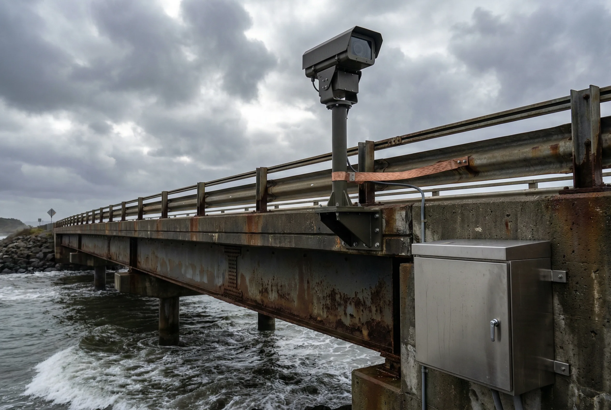
Figure 3.5: Bridge surveillance — camera pole on bridge parapet with vibration-damping mount, copper grounding strap bonded to bridge steel, stainless steel cabinet with anti-salt-fog coating. Coastal environment with wave action visible.
Bridge deployments combine three challenging environmental factors: structural vibration from traffic and wind, salt-fog corrosion in coastal locations, and the difficulty of routing power and fiber cables across expansion joints. PTZ cameras on bridges must have image stabilization to compensate for structural vibration, which can be significant on long-span bridges during heavy traffic or wind events. Fixed cameras must use vibration-damping mounting brackets to prevent image blur.
All hardware on coastal bridges must be rated for salt-fog exposure, using stainless steel or hot-dip galvanized steel for mounting hardware, stainless steel cabinets with enhanced sealing, and corrosion-resistant coatings on camera housings. Grounding must be bonded to the bridge steel structure using copper flat straps, and the grounding resistance must be verified after installation. Cable routing across expansion joints requires flexible conduit sections to prevent cable fatigue failure.
| Indicator | Specification | Acceptance Method |
|---|---|---|
| Image stability | No blur from structural vibration at design wind speed | Image review during high-wind event; stabilization test |
| Salt-fog protection | IEC 60068-2-11 ≥ 500 h; no corrosion after 1 year | Certificate verification; 1-year visual inspection |
| Grounding resistance | < 4 Ω at all bonding points | Earth resistance tester measurement after installation |
| Expansion joint cable | Flexible conduit; no cable fatigue after 6 months | Visual inspection; cable continuity test |
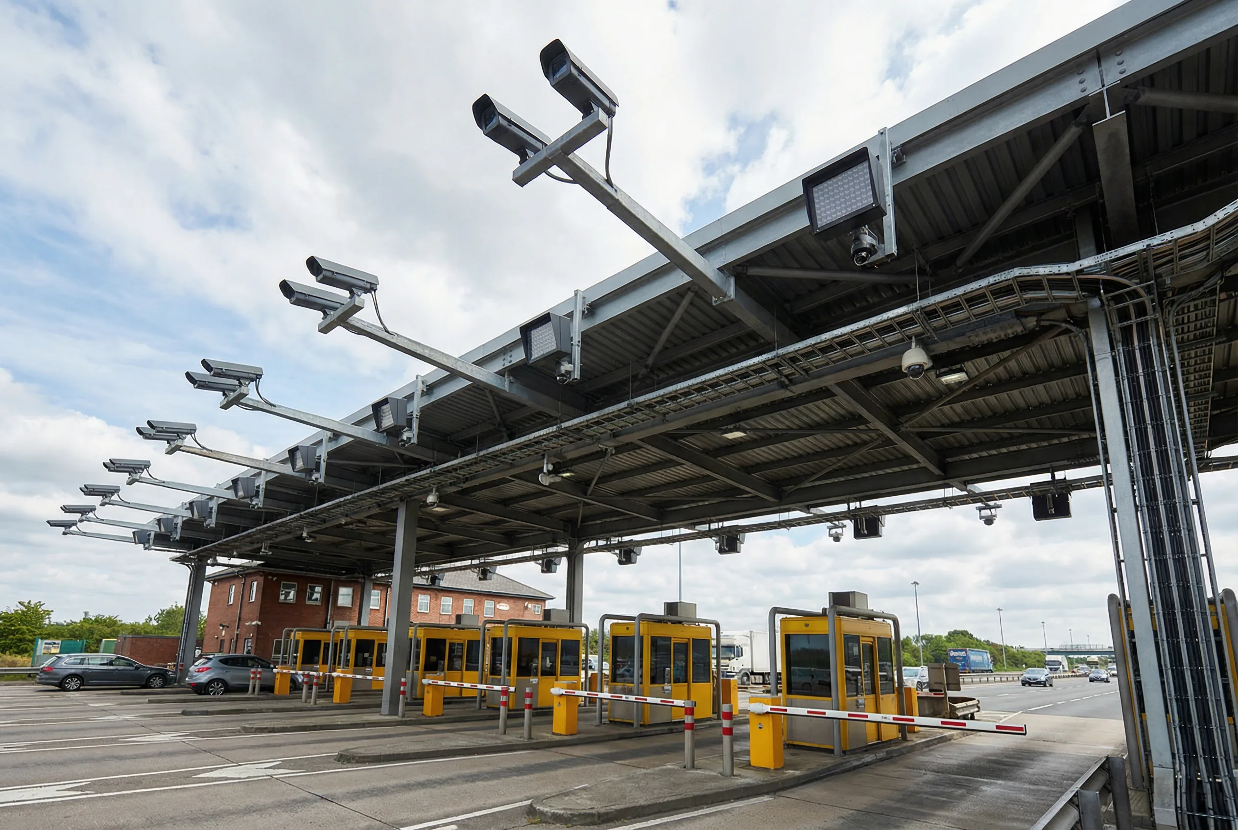
Figure 3.6: Toll plaza surveillance — overhead canopy with per-lane ANPR cameras and IR illuminators, lane overview cameras, and cable tray routing to the toll building. Multiple lanes with barrier gates visible.
Toll station surveillance is characterized by high camera density — typically one ANPR camera per lane plus one overview camera per two lanes — and the need for tight integration with the toll collection system for transaction correlation. Each lane requires a dedicated ANPR camera mounted overhead, aimed at the license plate position at the barrier gate, with an IR illuminator sized for the lane width. The overview cameras provide situational context and support incident detection in the plaza area.
The toll building provides a convenient aggregation point for all camera feeds, power distribution, and fiber backhaul. The edge switch in the toll building aggregates all lane cameras and connects to the central platform via the highway fiber ring. The toll system integration requires a real-time API connection to correlate ANPR captures with transaction records, enabling both fee evasion detection and evidence export for disputes.
| Indicator | Specification | Acceptance Method |
|---|---|---|
| Plate capture rate | ≥ 98% day and night | 100-vehicle drive-through test each condition |
| Transaction correlation | ANPR capture matched to toll record within 1 s | Correlation accuracy test with 100 transactions |
| Fee evasion detection | ≥ 95% detection rate; < 2% false alarm | Controlled evasion test with test vehicles |
| Evidence export | Complete evidence package within 5 min of request | Export time measurement; hash verification |
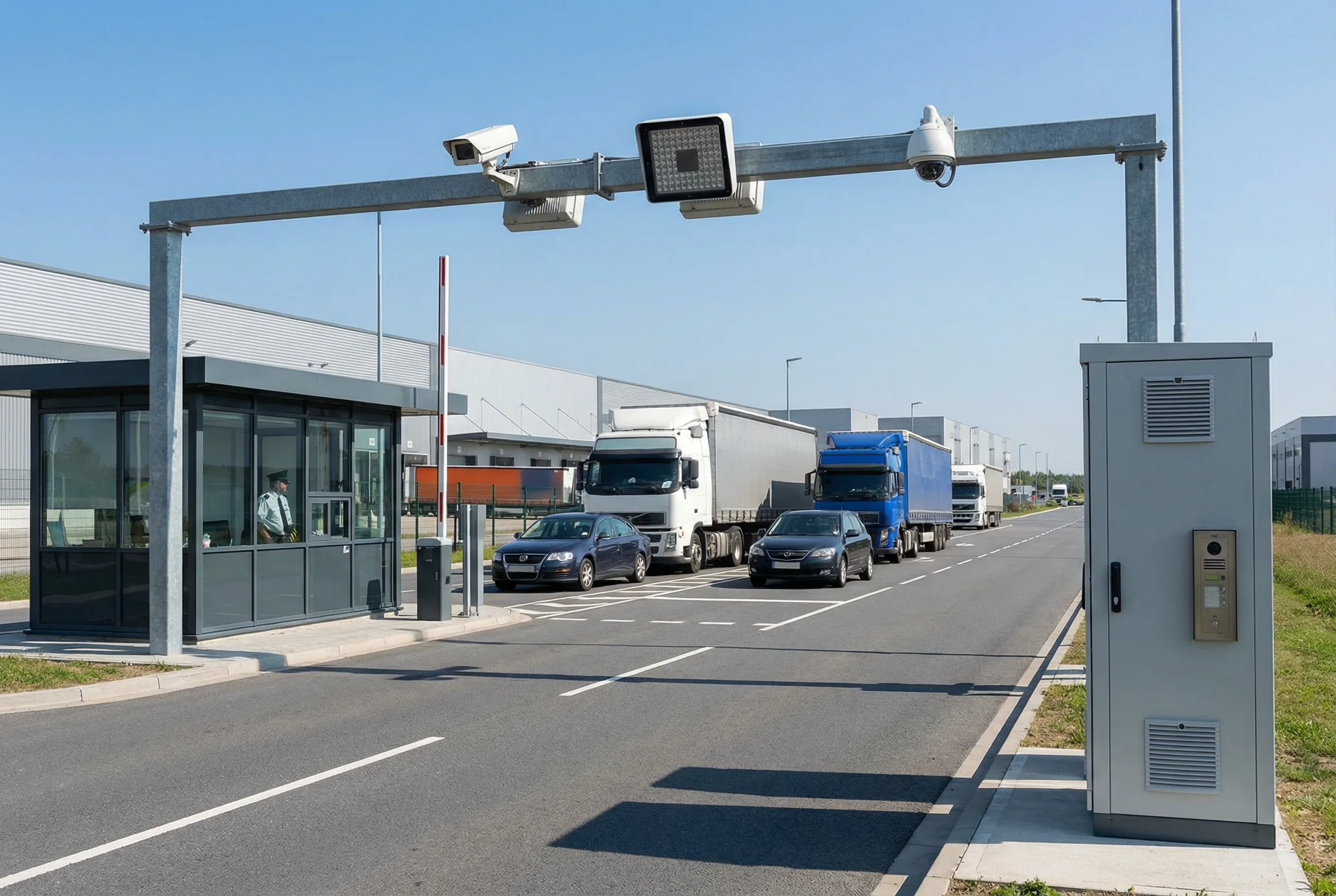
Figure 3.7: Industrial park entrance — overhead gantry with ANPR camera, IR illuminator, and dome overview camera. Security booth, barrier gate, and access control intercom visible. Trucks and cars queuing at the controlled access point.
Industrial park entrance surveillance combines ANPR-based access control with general surveillance, creating a system that must simultaneously serve security, logistics management, and safety functions. The ANPR camera captures license plates for whitelist/blacklist matching and access control decisions, while the overview camera provides situational context for the security booth operator. The integration with the access control system must be real-time, with the barrier gate opening within 2–3 seconds of a whitelist match.
The entrance environment typically has lower vehicle speeds (5–20 km/h) than highway deployments, which relaxes the shutter speed requirement but introduces new challenges: vehicles may stop partially in the camera field of view, creating occlusion; heavy trucks may block the camera view of following vehicles; and the entrance may be used by both vehicles and pedestrians, requiring separate coverage zones. The system must also handle the logistics use case of recording vehicle entry/exit times and correlating them with delivery records.
| Indicator | Specification | Acceptance Method |
|---|---|---|
| Plate recognition rate | ≥ 99% for whitelist vehicles | 100-vehicle test with registered plates |
| Barrier response time | ≤ 3 s from plate recognition to gate open | Stopwatch measurement; 20 test passes |
| Access log retention | ≥ 90 days; exportable with timestamp | Log audit; export and hash verification |
| Truck occlusion | Following vehicle captured after truck clears | Truck + car sequential entry test |
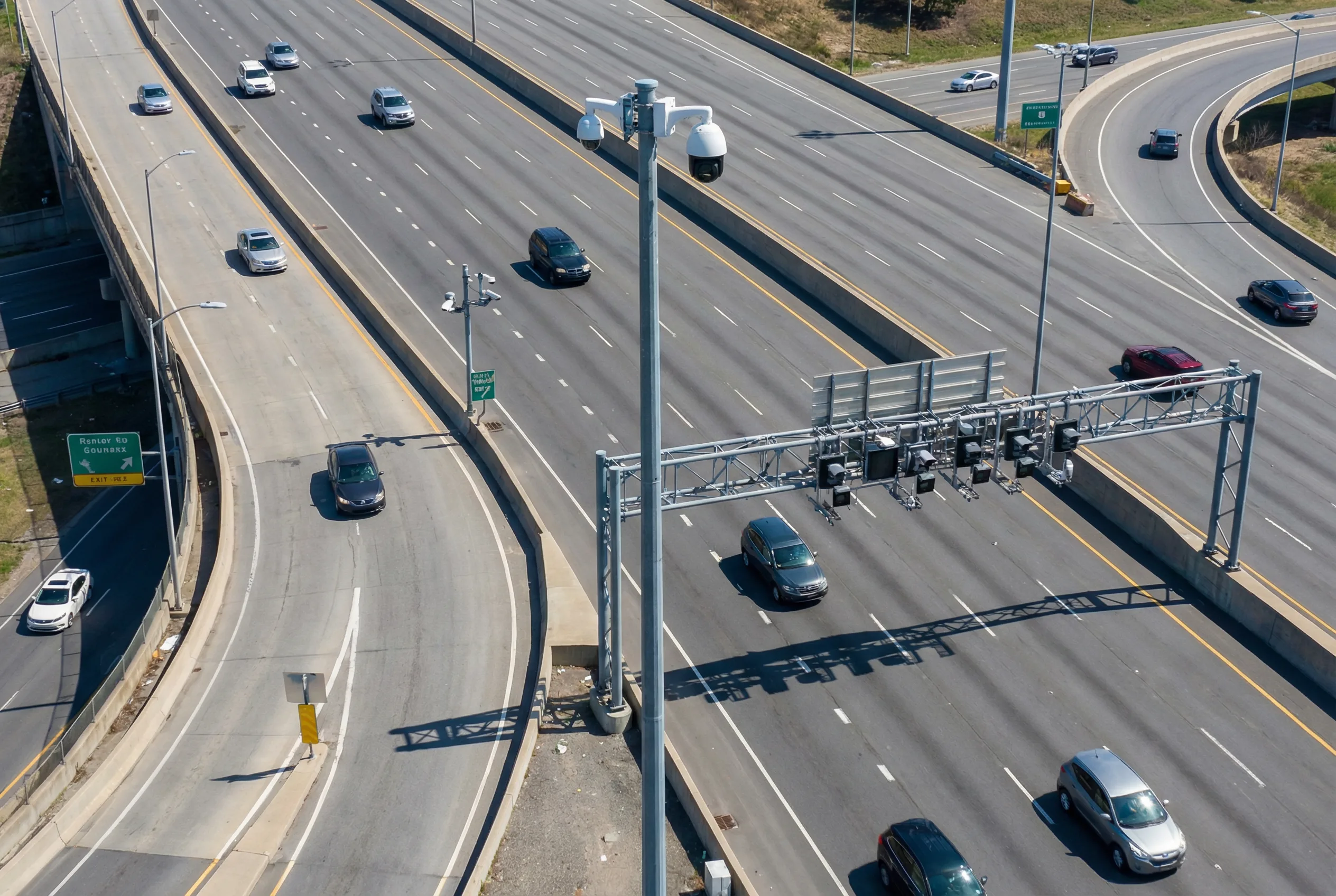
Figure 3.8: Highway ramp and interchange surveillance — PTZ camera on tall pole for wide-area overview, overhead gantry with per-lane cameras at the merge zone, and ramp entry camera. Complex geometry with speed differential between highway and ramp.
Highway ramp and interchange zones are high-risk areas where traffic incidents are disproportionately frequent due to speed differentials, lane changes, and driver attention demands. Surveillance coverage must address three distinct zones: the ramp entry zone, where vehicles transition from surface road speeds to highway speeds; the merge/weave zone, where vehicles must find gaps in the highway traffic stream; and the diverge zone, where vehicles must decelerate and exit. Each zone has different camera requirements and coverage geometry.
The complex geometry of interchange ramps — with curves, grade changes, and sight-line obstructions — makes camera placement challenging. A PTZ camera on a tall pole (8–12 m) provides wide-area situational awareness and can be directed to any zone on operator command. Fixed cameras at the ramp entry and merge point provide continuous recording for evidence and analytics. The overhead gantry at the merge point is the preferred mounting location for per-lane cameras, as it provides a consistent overhead view of the merge zone.
| Indicator | Specification | Acceptance Method |
|---|---|---|
| Coverage completeness | No blind spots in merge/weave zone | Walk-through with calibration target; camera overlap check |
| Wrong-way detection | ≥ 95% detection rate; < 1 false alarm/day | Controlled test with test vehicle; 7-day baseline |
| PTZ preset accuracy | ± 0.1° repeatability; preset call < 3 s | Preset accuracy test; 20 preset calls each position |
| Incident alarm latency | Alarm within 10 s of incident onset | Controlled incident simulation; timestamp measurement |
Scenario Selection Matrix
The following matrix provides a quick-reference comparison of the eight scenarios across the key selection dimensions. Use this matrix as a starting point for scenario classification, then refer to the detailed scenario descriptions above for specific design guidance.
| Scenario | Speed | WDR Need | IR Need | Analytics | Integration | Key Risk |
|---|---|---|---|---|---|---|
| 1. Urban Intersection | 30–60 km/h | Very High | Medium | Violation, pedestrian | Signal controller | Backlight washout |
| 2. Highway Mainline | 80–120 km/h | High | High | Incident, congestion | TMC platform | Motion blur at speed |
| 3. Tunnel Portal | 60–100 km/h | Extreme | Low | Smoke/fire, ANPR | Tunnel SCADA | Portal transition failure |
| 4. Tunnel Interior | 60–100 km/h | Low | Low | Smoke, stopped vehicle | Tunnel SCADA, VMS | Soot degradation |
| 5. Bridge Section | 60–100 km/h | Medium | Medium | Incident, wrong-way | TMC platform | Vibration blur, corrosion |
| 6. Toll Station | 5–40 km/h | Medium | High | ANPR, fee evasion | Toll system, ETC | Lane occlusion |
| 7. Industrial Entrance | 5–20 km/h | Medium | Medium | ANPR, access control | Access control, logistics | Truck occlusion |
| 8. Ramp & Interchange | 0–120 km/h | High | Medium | Wrong-way, merge conflict | TMC, signal controller | Complex geometry coverage |