Chapter 4. Architecture Design
Typical system topology, network architecture, and equipment wiring for road video surveillance systems
The architecture of a road video surveillance system determines its scalability, resilience, and operational performance over its entire service life. A well-designed architecture separates the field layer (cameras and local equipment), the aggregation layer (fiber ring and aggregation switches), and the central layer (servers, storage, and management platform) into clearly defined tiers with standardized interfaces between them. This layered approach enables independent scaling of each tier, simplifies troubleshooting, and allows technology refresh of individual components without disrupting the entire system.
4.1 Three-Layer Architecture Overview
The three-layer architecture is the industry-standard approach for road surveillance systems of any significant scale. The field layer consists of all cameras, illuminators, and local processing equipment at each surveillance point. The aggregation layer provides the fiber ring network that connects all field nodes to the central facility. The central layer hosts the video management system, storage arrays, analytics servers, and operator workstations. Each layer has distinct design requirements, equipment specifications, and failure modes.
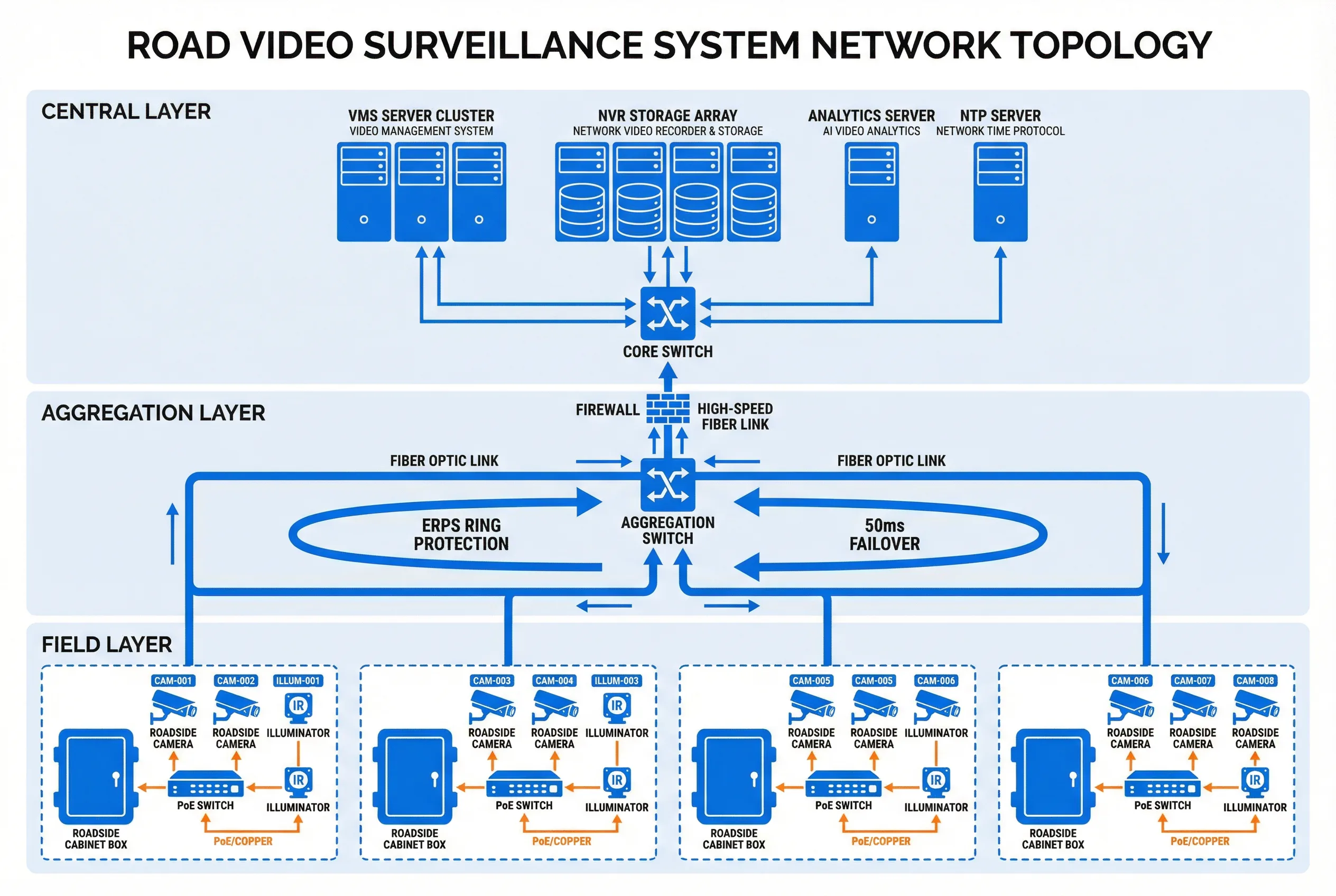
Figure 4.1: Three-layer network topology for a road video surveillance system — Field Layer (cameras and roadside cabinets), Aggregation Layer (ERPS fiber ring), and Central Layer (VMS, NVR, and analytics servers). Blue lines represent fiber connections; orange lines represent PoE/copper connections.
The topology diagram above illustrates the standard three-layer architecture. At the field layer, each surveillance point consists of a roadside cabinet containing an industrial PoE switch, which connects to the cameras via Cat6 cable. The roadside cabinet also contains a surge protection device, a circuit breaker, and optionally a UPS battery for short-duration power backup. The aggregation layer uses an ERPS (Ethernet Ring Protection Switching) fiber ring, which provides automatic failover in less than 50 milliseconds when a fiber link is cut. The central layer aggregates all camera streams through a core switch and distributes them to the VMS, NVR storage, and analytics servers.
4.2 Typical System Topology Variants
While the three-layer architecture is the standard, the specific topology varies with the scale and geography of the deployment. The following table summarizes the four most common topology variants and their applicability.
| Topology | Scale | Fiber Architecture | Failover | Typical Application |
|---|---|---|---|---|
| Single Ring | Up to 20 nodes | Single ERPS ring | < 50 ms | Urban arterial corridor, short highway section |
| Dual Ring | 20–50 nodes | Primary + backup ring | < 50 ms | Long highway corridor, city-wide network |
| Star + Ring | 50–200 nodes | Aggregation rings + star to core | < 50 ms ring; < 1 s star | Large city network, provincial highway |
| Hierarchical | 200+ nodes | Multi-level rings; MPLS core | < 50 ms per ring | National highway network, metropolitan area |
4.3 Roadside Cabinet Wiring Design
The roadside cabinet is the fundamental building block of the field layer. Its internal wiring design determines the reliability, maintainability, and safety of each surveillance point. A well-designed cabinet separates power and data circuits, provides proper surge protection on all external connections, and includes clear labeling and cable management to facilitate maintenance. The following diagram shows the standard wiring layout for a roadside surveillance cabinet.
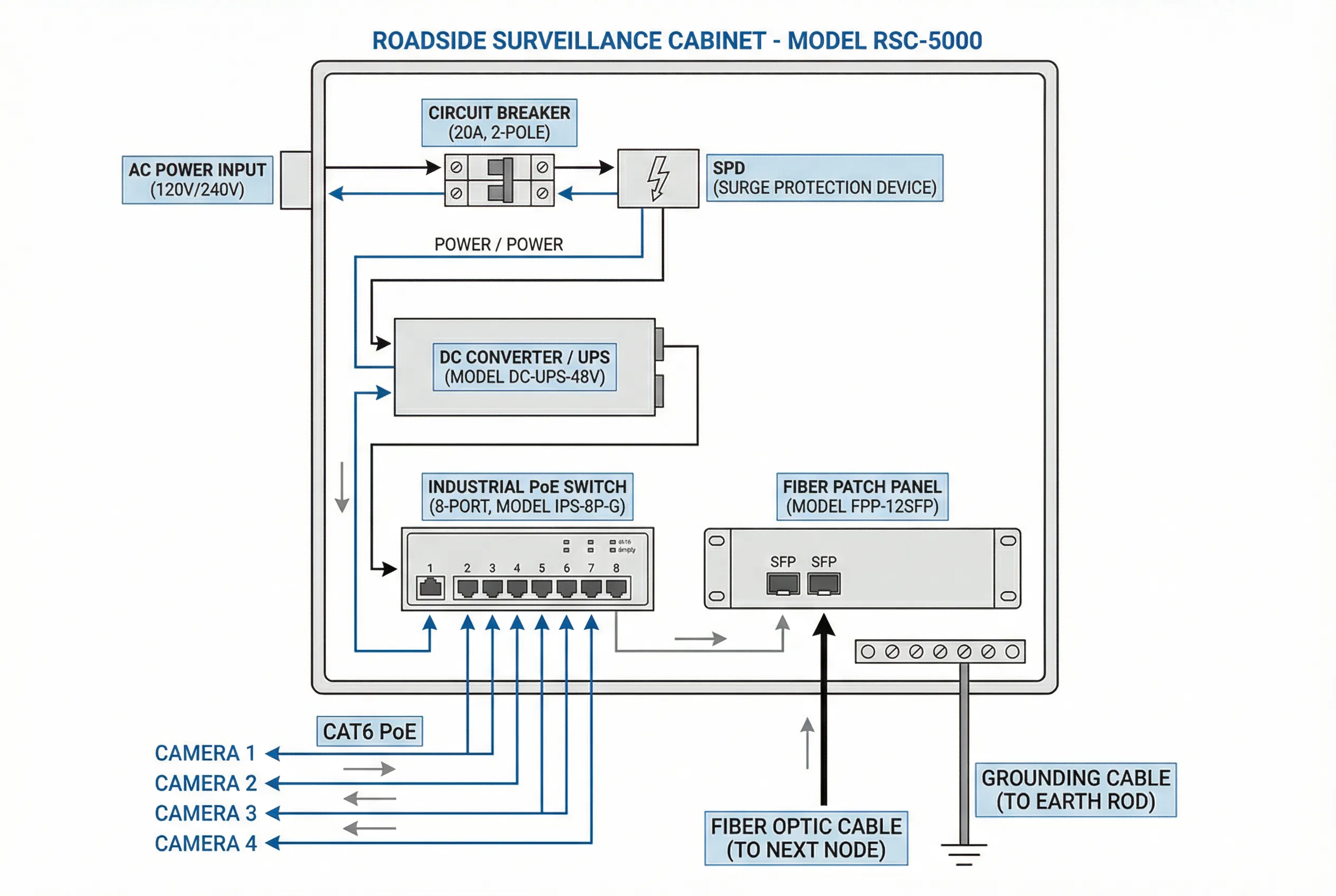
Figure 4.2: Roadside surveillance cabinet internal wiring diagram — AC power input with circuit breaker and SPD, DC converter/UPS, industrial PoE switch with camera connections, fiber patch panel with SFP uplinks, and grounding cable to earth rod. All connections labeled with cable type and specifications.
The wiring diagram illustrates the standard internal layout of a roadside surveillance cabinet. AC power enters through a circuit breaker and surge protection device (SPD) at the top. The DC converter or UPS provides regulated power to the PoE switch and other DC-powered equipment. The industrial PoE switch connects to cameras via Cat6 cable, providing both power and data over a single cable run. The fiber patch panel connects to the ERPS ring via SFP transceivers, providing the uplink to the aggregation layer. All equipment is bonded to the cabinet chassis, which is connected to the earth rod via a copper grounding cable.
4.4 Network Design Parameters
The network design must be sized to handle the aggregate bandwidth of all cameras at their maximum bitrate, with headroom for management traffic, analytics streams, and future expansion. The following table provides the key network design parameters for typical camera configurations.
| Parameter | Value / Formula | Notes |
|---|---|---|
| Camera stream bitrate (4MP, H.265) | 2–4 Mbps per camera | Main stream; sub-stream 512 kbps |
| Aggregate bandwidth per node | N × 4 Mbps × 1.2 (overhead) | N = number of cameras at node |
| Ring segment bandwidth | Sum of all upstream node bandwidth | Must not exceed 80% of ring capacity |
| Ring capacity (1G fiber) | 800 Mbps usable (80% of 1G) | Supports ~200 cameras per ring segment |
| Ring capacity (10G fiber) | 8 Gbps usable | Supports ~2000 cameras per ring segment |
| ERPS failover time | < 50 ms | ITU-T G.8032 standard |
| NTP synchronization accuracy | ± 1 ms to GPS reference | Required for evidence-grade timestamps |
| Management VLAN | Separate VLAN from video traffic | Prevents management lockout during congestion |
4.5 Power Architecture and Redundancy
Power reliability is the single most important factor in field equipment availability. Highway surveillance points are typically served by the highway power supply, which has its own redundancy provisions. Urban surveillance points may be served by street lighting circuits, which are less reliable. In both cases, the roadside cabinet should include a UPS with sufficient capacity to maintain operation during short power outages (typically 15–30 minutes), and the UPS battery must be sized for the thermal environment of the deployment location.
| Power Component | Specification | Selection Criterion |
|---|---|---|
| Circuit breaker | 20A, 2-pole; rated for outdoor use | Size for 125% of maximum load current |
| SPD (AC side) | Type 2; Uc ≥ 275V; Imax ≥ 20 kA | Match to local lightning exposure level |
| DC converter | AC 220V to DC 48V; efficiency ≥ 90% | Size for 150% of PoE switch maximum load |
| UPS battery | 12V VRLA; capacity for 30 min at full load | Derate for temperature: -20% per 10°C above 25°C |
| PoE switch power budget | ≥ 30W per port; total budget ≥ N × 25W | N = number of cameras; 25W per camera typical |
| Cabinet thermal | Fan + thermostat; internal ≤ 55°C at 40°C ambient | Calculate heat load: sum of all equipment dissipation |
4.6 Grounding and Lightning Protection
Grounding and lightning protection are critical for the long-term reliability of field equipment. Road surveillance equipment is exposed to lightning strikes both directly (via the camera and pole) and indirectly (via induced surges on power and data cables). A comprehensive protection scheme includes lightning rods on tall poles, SPDs on all external connections, and a low-resistance earth ground at each cabinet. The grounding system must be designed and tested to achieve a resistance of less than 4 Ω at each cabinet, and the SPDs must be inspected and replaced after any significant lightning event.
| Protection Level | Component | Specification |
|---|---|---|
| Primary (direct strike) | Lightning rod on pole | Franklin rod; protection angle per IEC 62305 |
| Secondary (AC power) | SPD Type 1+2 at cabinet entry | Iimp ≥ 12.5 kA; Uc ≥ 275V AC |
| Tertiary (data/PoE) | SPD on each PoE port | Imax ≥ 10 kA; clamping voltage ≤ 50V |
| Fiber uplink | No SPD needed (dielectric fiber) | Use dielectric fiber cable; no metallic elements |
| Earth ground | Copper earth rod + flat strap | Resistance < 4 Ω; verified with earth tester |
| Equipotential bonding | All metal parts bonded to cabinet chassis | Bonding resistance < 0.1 Ω between any two points |